The other two R640s
The Firewheel project has three of these servers. Server 3 (2N3XQJ3) has its own document. This one covers the remaining two, each on its own: what the photos show inside, and what each one needs before it can be switched on. Neither is ready yet. Server 1 needs drive carriers and a cover for its empty processor socket. Server 2 has no fans and no drives.
Server 1: one processor, four bare drives
JM3XQJ3Inside and front photographed 21 November 2026, back on 15 November.
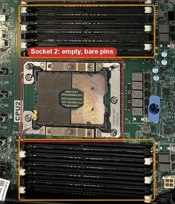
- Cover processor socket 2. Its pins are bare, and a touch bends them for good. Dell's manual calls for a CPU dust cover and a processor blank on an empty socket, or fit a second processor with a heatsink.
- Drive carriers for the four drives. They sit in the bays loose, with no Dell carriers to hold them against the connectors. Fit 2.5-inch carriers for Dell's 14th-generation servers, or take the drives out.
- Blank covers for bays 0 and 1. They are open, so air skips the drives.
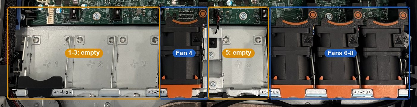
- A fan or a fan blank in bays 1, 2, 3 and 5. Dell's service manual says every fan bay must always hold a fan or a blank. Server 3 left Dell with five fans for one processor, so check iDRAC for a fan warning at the first power-on.
Inside
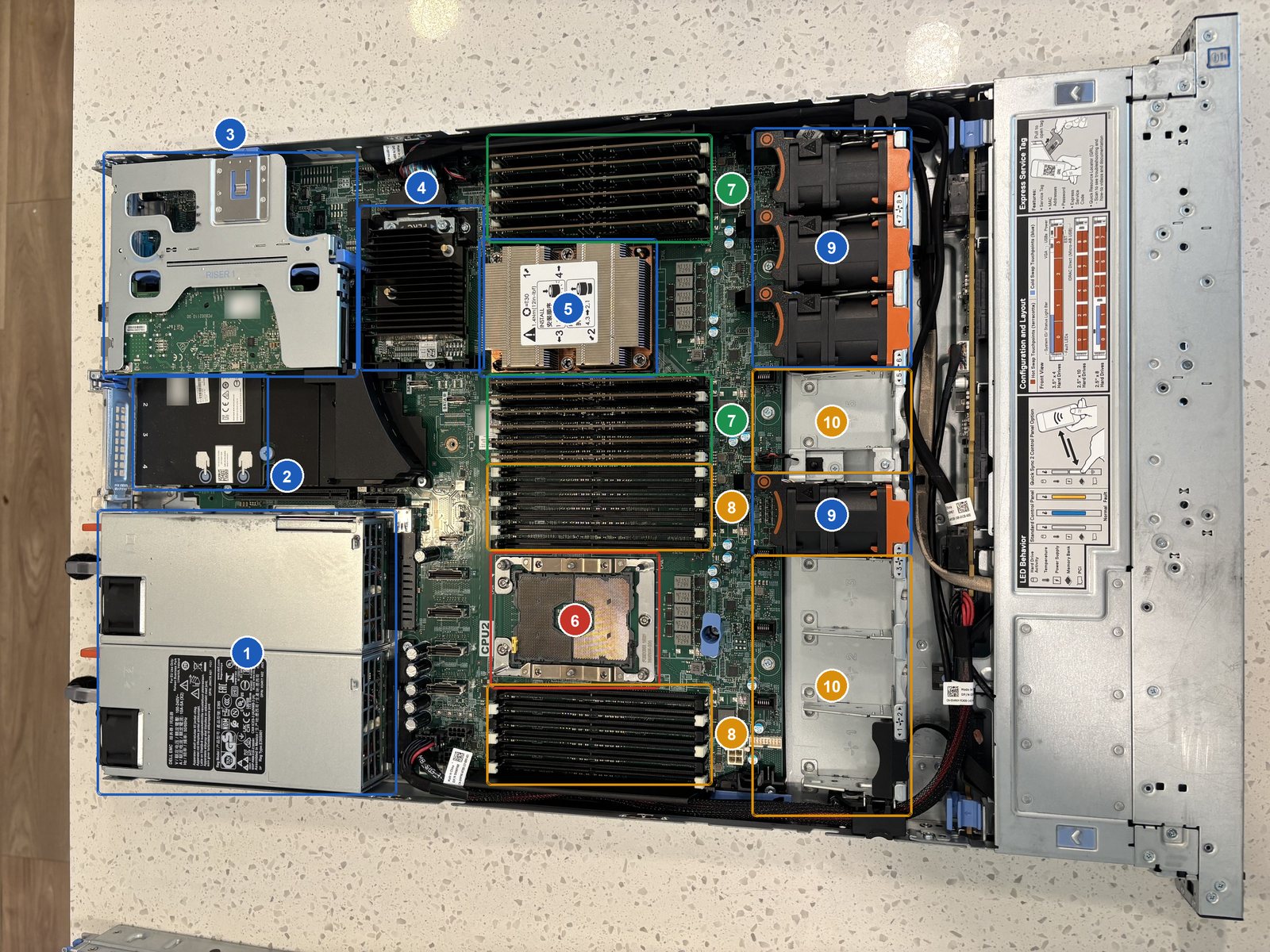
- 1Two power supplies
750 W each, rated 100-240 V, so a normal wall outlet works.
- 2Built-in network card
Two 10 Gb and two 1 Gb Ethernet ports on the back.
- 3Riser 1, with a fiber card
Mellanox ConnectX-4 Lx (label: model CX4121A), two fiber ports, in slot 2. Slot 1 has a cover.
- 4PERC RAID card
Runs the drives. Its model label is under the heatsink.
- 5Processor 1
Under the heatsink. The model shows at power-on.
- 6Socket 2: empty, bare pins
No processor and no protective cover.
- 712 memory sticks
Six on each side of processor 1: every slot it can use.
- 812 empty memory slots
These belong to processor 2 and only work once a second processor is fitted.
- 9Four fans
In bays 4, 6, 7 and 8.
- 10Empty fan bays
Bays 1, 2, 3 and 5.
Front and back


Server 2: two processors, no fans, no drives
HM3XQJ3Inside and front photographed 21 November 2026, back on 15 November.
- Eight fans. Every fan bay is empty. Do not switch it on until they are in: nothing would cool the processors. Server 3 has the same two-processor layout and runs all eight.
- Drives and carriers. It has none. The drive plan on server 3 (two SSDs plus hard drives) would fit here too.
- Blank covers for any bay left open among bays 0 to 3.
Inside
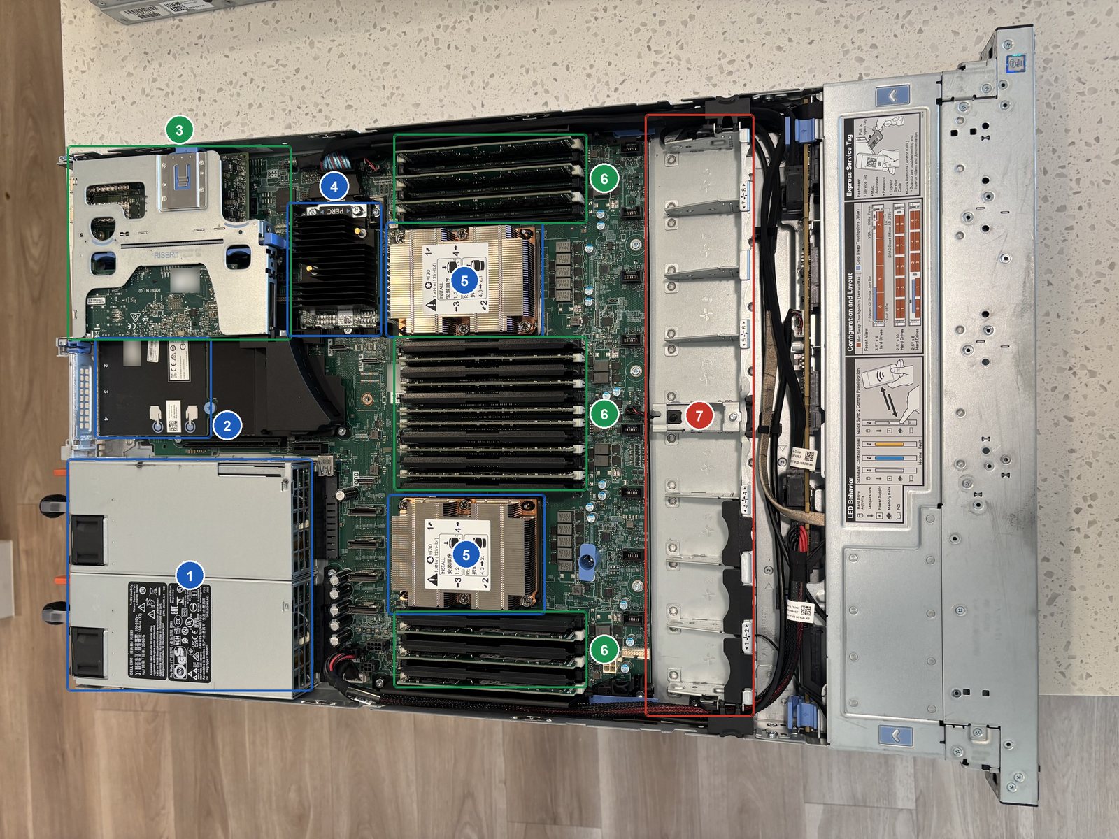
- 1Two power supplies
750 W each, rated 100-240 V, so a normal wall outlet works.
- 2Built-in network card
Two 10 Gb and two 1 Gb Ethernet ports on the back.
- 3Riser 1, with two fiber cards
Slots 1 and 2. One is labeled Mellanox ConnectX-4 Lx, model CX4121A.
- 4PERC RAID card
Runs the drives. Its model label is under the heatsink.
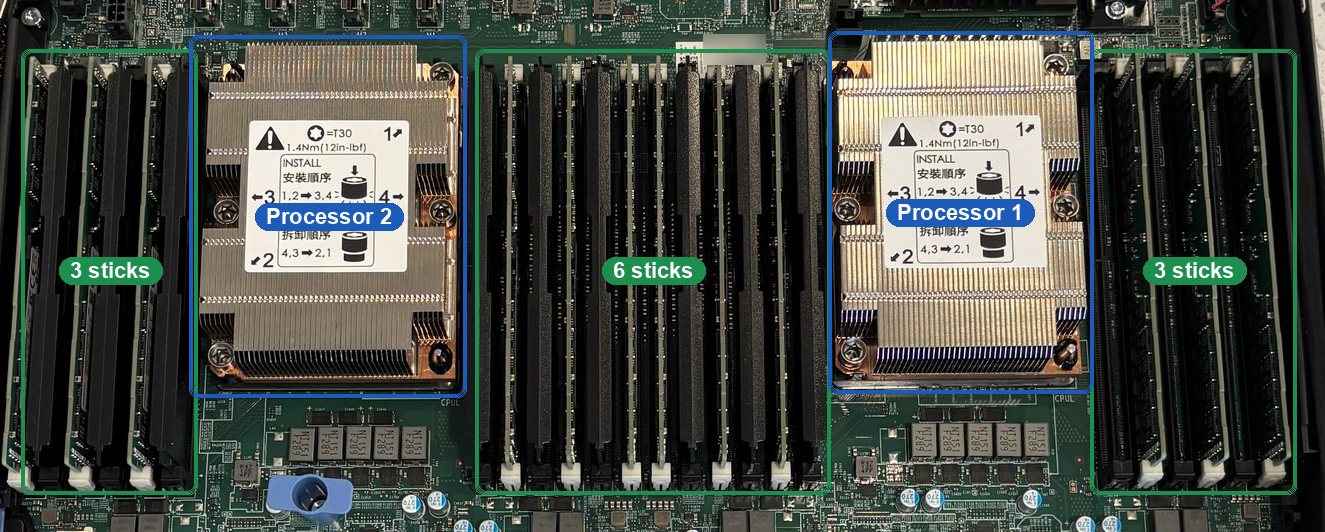
- 5Two processors
Each under a heatsink. Models show at power-on.
- 612 memory sticks
3, 6 and 3 across the three banks: every other slot, six per processor.
- 7No fans
All eight fan bays are empty.
Front and back


Side by side
| Part | Server 1 · JM3XQJ3 | Server 2 · HM3XQJ3 |
|---|---|---|
| Processors | 1. Socket 2 empty, pins barecover it | 2 |
| Memory | 12 sticks, all on processor 1 | 12 sticks, 6 per processor |
| Fans | 4 of 84 bays need a fan or blank | 0 of 8needs 8 |
| Drives | 4 bare drives, bays 2-5needs carriers | Noneneeds drives |
| Open drive bays | 0 and 1 | 0 to 3 |
| RAID card | PERC mini card | PERC mini card |
| Add-in cards | 1 fiber card (slot 2), 1 module | 2 fiber cards (slots 1-2), 2 modules |
| Built-in network | 2 × 10 Gb + 2 × 1 Gb RJ45 | 2 × 10 Gb + 2 × 1 Gb RJ45 |
| Power supplies | 2 × 750 W Platinum | 2 × 750 W Platinum |
| Still to read at power-on | Processor model, memory size, drive sizes | Processor models, memory size (after fans go in) |
At the first power-on, press F2 while it starts: System BIOS, Processor Settings and Memory Settings show the processors and the memory total, and Device Settings, the PERC entry, lists the drives.